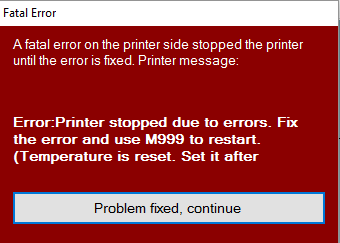
This week I was printing out a Recorder to add to my growing 3D Printed instrument collection when I was greeted with this very foreboding screen:
That’s a scary error message.
My 3D printer encountered a fatal error as the popup pointed out. Luckily the printer shut everything down or else something bad might have happened. This popup isn’t really very revealing about what that fatal error was however so I had to check the print log to see what exactly the error was. I was greeted with this:
The line is question is the second one: MINTEMP triggered ! Turns out the printer was reading the extruder temperature as zero degrees Celsius, not the temperature you want for melting plastic. So this meant that the failure occurred at either two parts of the temperature reading chain, either it was an issue with the electronics, either the RAMPS port or Arduino Mega analog circuitry was fried, or the thermistor itself was broken. The RAMPS port shorting out wouldn’t have been a big deal I could have used the other available port usually reserved for a second extruder and just switched it over in the firmware. However I was able to rule out an issue on the electronic’s side by attaching a 100k Ohm resistor to the RAMPS port and it got a reading of 20 degrees C. I was able to test because Thermistors are just resistors where the resistance reacts to the temperature, hence their name.
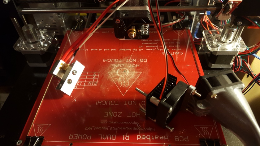
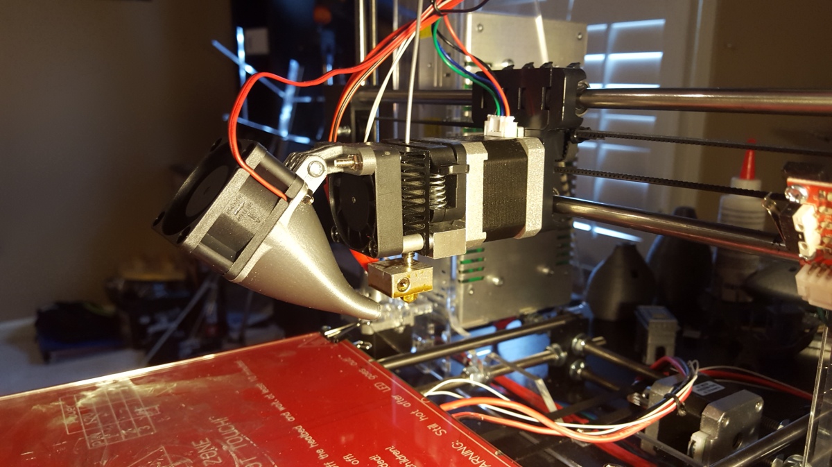
It was time to disassemble the extruder! I took off my cooling setup to be able to get at the nozzle, which is not a big deal at all, it only required removal of two screws.
Odd how only two screws hold this entire thing together.
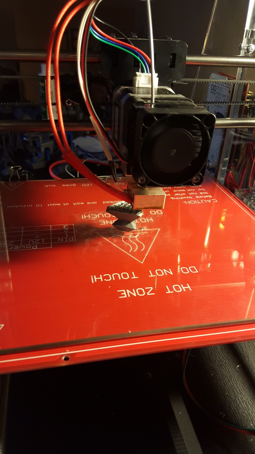
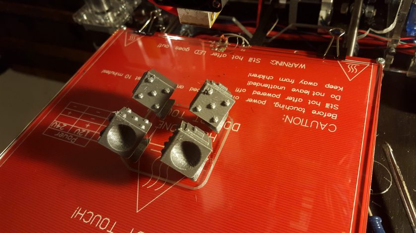
The thermistor is the white wires coming from the nozzle seen at the left. I was worried I might have to buy an whole new nozzle assembly but they are also very easy to remove, you only need to loosen a small hex screw on the side of the nozzle.
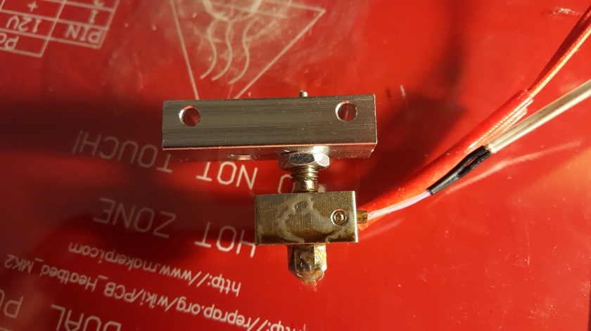
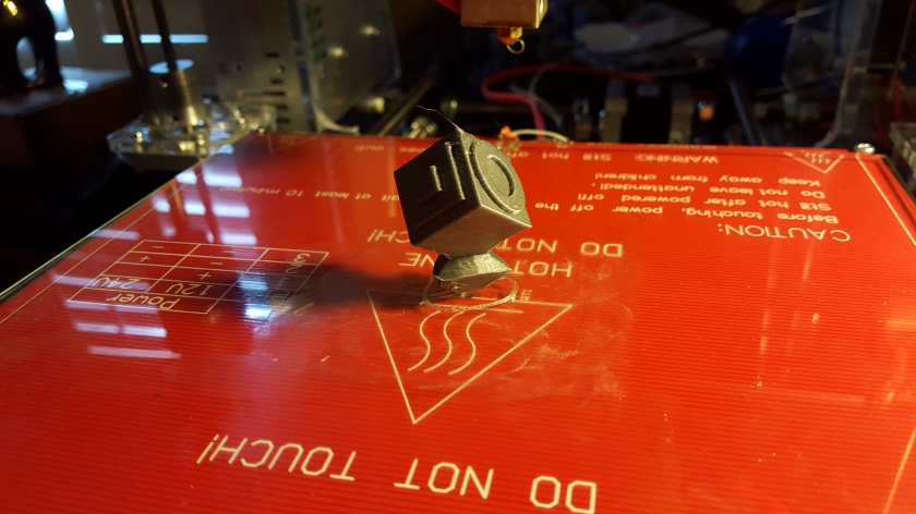
Don’t worry I cleaned the nozzle and heated bed very well after this.
You can see the screw there keeping the thermistor in place. A visual inspection of the thermistor didn’t reveal much but testing it for resistance with my multimeter confirmed it was dead. Luckily for me, a replacement was only a 2 day amazon shipping away. I got a pack of five for 7 dollars which I’d consider pretty fair, especially if there’s any more failures like this.
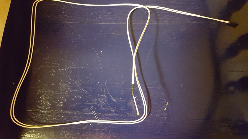
I think the replacement’s wires have better sleeving anyways.
After installing the new one I was able to connect to the printer in Repetier without the red message of doom appearing, and it actually read the temperature accurately.
Its alive!
This update was a bit shorter than normal, probably because this repair didn’t take long at all. I’ll be back on track printing stuff now so we will hopefully see more developments in future updates. See you then!
As you might recall from last time, I was in the process of printing a fan duct to mount my cooling fan on my 3D Printer. Since then I’ve been able to run a couple of tests to see how it improves my print quality, and I’m extremely happy with the results.
The First Test: 0.2 Layer Height
Inspired by the comparison photos taken from the thingiverse file’s own upload, I decided to test the tree frog model at 0.2 layer height with and without the fan. The results of this test were… less than exciting.
This slideshow requires JavaScript.
As you can see from the two images… there was very little difference in this print. The one on the left was printed without the cooling fan. The reason I believed this would be a good test was because it is such an organic shape and has a pretty major overhang with the body of the frog. Also PLA is typically known to have huge issues with printing overhangs without a cooling system so I thought that the print without a fan might even outright fail. Turns out I was printing the PLA at a cool enough temperature to allow for passive cooling to let the overhangs print.
The Second Test: 0.1 Layer Height Part 1
While the test at a 200 micron layer height wasn’t as exciting as I had hoped, I decided to test out how the fan effects prints at 0.1 mm layer heights. For my first model I chose Benchy, as its a staple in 3D printing benchmarks. This test proved much more fruitful, and helped validate the installation of the fan, as the improvements are crazy.
This slideshow requires JavaScript.
Obviously the image on the left was printed without a cooling fan, and both were done with the exact same slicing settings, which I think is pretty interesting. Clearly the importance of a cooling fan becomes apparent when you start to print with smaller layer heights. I think this has something to do with the plastic still being heated due to being so close to the nozzle but that’s just my theory. You can tell there are some issues with the part being printed with the fan on the smoke stack and the little circle in the back due to some stringing. I still have a lot of work to do fixing that issue, but other than that I’m enthralled at the quality, especially the bottom and right facing profile images show the uniformity and smoothness achieved by the low layer height combined with the cooling fan.
The Third Test: 0.1 Layer Height Part 2
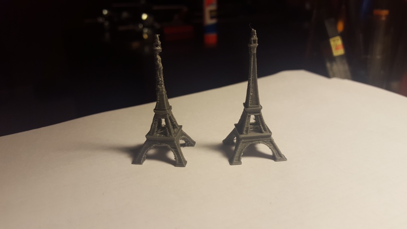
For my final test I returned to my personal 3D Printing standard of quality, the tiny Eiffel Tower. This tower was the first print I ever did, though it didn’t come out so well. In retrospect its clear why, this is a pretty tricky print as it has its fair share of minute details and the tower is so thin its subject to overheat very quickly, especially near the top. You may recall I eventually got it looking pretty good at 0.2 layer height, but when graduating to a 0.1 layer height all these problems were magnified. The cooling fan has essentially solved all those issues, and was able to bring out all the detail in the base and in the top without overheating at all. I really cannot understate how much of an improvement the cooling fan makes for printing at smaller layer heights.
The top of the one on the right looks like a witch’s hat or something
Once again the good one printed with the cooling fan is on the right, and there’s a bit of stringing present but overall the detail is far better than anything I’ve printed before.
Installation and Configuration
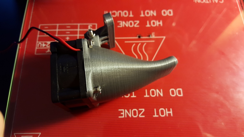
The fully assembled and mounted cooling fan
First off, I used this model from thingiverse, and its been working great. The only trouble I had with it was I needed to use a drill to widen the screw holes a bit. Other than that assembly was very simple. I was also lucky that my extruder fan had 2 free screw holes to mount it to.
The fully assembled cooling system
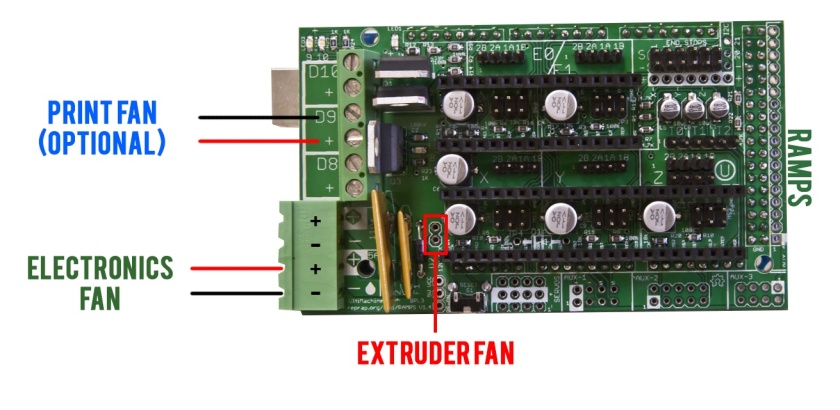
The fan itself should be connected to the D9 Terminal on your RAMPS 1.4 board, so the slicer software can directly control it. The extruder fan, the one directly on the extruder and not pointing at the hotend, should be connected to the 12V auxiliary output located below the x motor stepper driver as shows below.
The reason for this is that the extruder fan should always be on to prevent the filament being extruded from getting to hot and clogging the system. The part fan is usually disabled for the first few layers to provide better bed adhesion and its output can be modulated to cool less while printing areas where a better seal between layers is needed, and more while printing overhangs or bridges.
There are also RAMPS addons that allow for multiple fans to be controlled at once for cooling multiple sides of the nozzle, cooling the RAMPS board itself to prevent the stepper drivers from overheating, or perhaps adding another nozzle for dual extrusion capabilities. Two options for this are described on a RepRap wiki here, this one being a bit more plug in play, while an open source design for a circuit board that accomplishes essentially the same thing is available here, though this one requires a bit more soldering if you choose to take it on.
Whats next?
The major improvements in print quality are making me think I might try to test the limits of my printer by printing some really small architectural objects, like the very popular Colosseum model. Also I’ve started printing a few very simple wind instruments and I might be doing some experiments relating to how different print settings change the sound quality of them. Thanks for reading and see you in the next update!
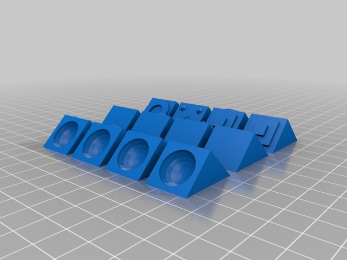
Up to this point my printing surface has been a glass plate on a heated bed, and I never gave it much thought as I have been printing exclusively in PLA and typically ABS plastic is known to have curling problems due to poor bed adhesion. As you might recall from my last 3d printing update I was going to print a fully printed functional Rubik’s Cube as one last test before I dived into creating instruments. Here’s a thingiverse link for the cube. Printing this Cube introduced me to a host of interesting 3D problems I hadn’t encountered before, and I’ll go into much more detail about how to solve them in later posts, but for this one lets focus on the two biggest that were both caused by poor bed adhesion.
1. Minimal Surface Area in Contact with the Print Bed
The result of numerous failed prints and giving in to the glue
Printing the corner pieces of the Rubik’s Cube was by far the most difficult part, as they had relatively complex shapes and as you can see, had a very, very small first layer. I cannot tell you how many times I had tried to print this piece only to watch it be knocked over by the nozzle. Initially I thought a lack of cooling was causing deformations in the overhangs, especially because previously the furthest the print ever got was here:
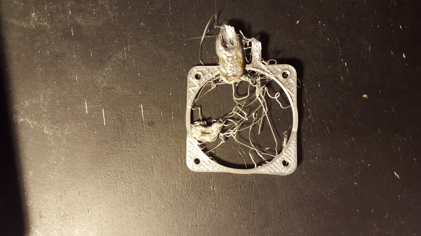
The overhang would become slightly deformed and result in failure. While that was part of the issue, cooling was not the only solution, and as you can see in the above picture, glue provided enough adhesion to keep the part in place. However, this print wasn’t actually what drove me to finally put glue on my print bed. I had been so convinced the failures were due to a lack of active cooling that I started printing an active cooling system to specifically this one. Well, turns out the fan duct had a pretty small surface area of contact as well, as my first two prints ended up like this:
The part of the print that caused the issue were the smaller pieces located at the top, they curled upwards and the nozzle started dragging around the print. After applying glue to the print bed however, the changed were immediately noticeable from the first layer all the way to, you know, actually finishing the print.
Notice the glue stick bathed in angelic light
So that’s the first challenge due to bed adhesion, now onto the second.
2. Printing Multiple Objects at Once
In order to speed up the printing process I opted to print out the provided files that had multiple parts to save time loading up each individual piece. This was the first time I had tried printing multiple pieces at once, and things took a turn for the worse real quick.
While the file may not look like a big deal, the problem with poor bed adhesion in this scenario is that if one print fails, they all go. In this case the pieces were spread out too far across the print bed and so they suffered uneven heating.
In this case we had combination of the two issues, both a small area in contact with the print bed and multiple objects. Luckily the glue was up to the challenge.
Putting it all Together
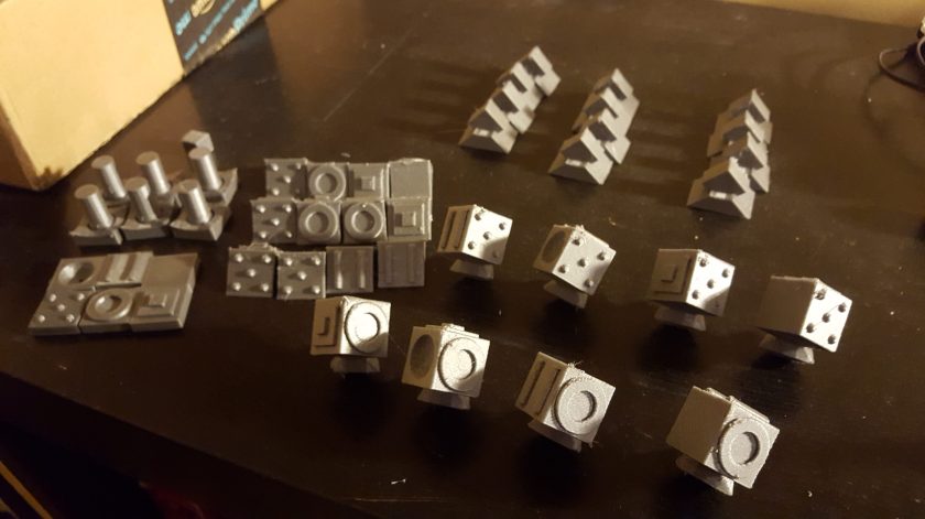
After many failed prints all the pieces to the Rubik’s Cube made it off the print bed intact and whole. This was a great print to do as it included some pretty tricky pieces as well as introduced me to printing multiple pieces at the same time.
As for how to print using glue, there’s a few things to keep in mind. First off, applying the glue is just as easy as it sounds, just run the glue stick over the area that will be printed on, shown below.
This might actually be a bit too much, but you get the idea
Once the print finishes, you’re more than likely not going to be able to just pop it off the glass. I take my glass bed off the heated plate and throw it in the fridge for 10 to 20 minutes depending on how big the object is, and the expansion of the plastic usually loosens it enough to be able to pry the print off. As for keeping the glass plate clean, warm water washes the glue off without any hassle. Due to this added time that your glass plate spends in the fridge or in the sink, it might be worthwhile to keep an extra one handy for hot swapping out if you want to print faster.
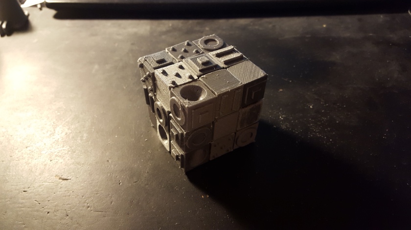
So I’ve found out that the glue stick is the way to go for my tricky prints. In the future I’m looking to print another Rubik’s Cube, this one using screws in the core and discussing applications of 3D Printing for creating functional objects that require interlocking and moving pieces. Though currently I’m printing a couple of simple wind instruments to do some experiments with the effect that different print settings have on the sonic quality of them. Until the next update, here’s a picture of the fully assembled and functioning cube 🙂
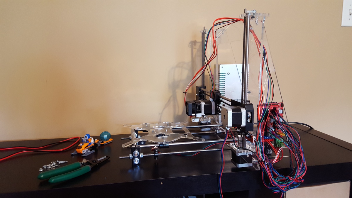
Now introducing one of the most important tools I have, perhaps second only to my computer, my 3D Printer.
What it is
My printer is a RepRap Prusa i3 Model, not the original Prusa i3 kit but from a company that specializes in selling RepRap parts, RepRap Guru. If you are unfamiliar with RepRap, its a community driven open source project where people submit and create 3D printing designs. RepRap itself is shorthand for Self-Replicating Rapid Prototyping Machine. Because the RepRap project is open source, all the schematics, bills of material, firmware, etc. are available for anyone to use. There are numerous RepRap designs out there that I’ll probably talk about later, but by far the most common one, and the one I have, is the Prusa i3. Originally designed by Josef Prusa, the third iteration of his design has essentially become synonymous with hobbyist or consumer 3D printing. His kit that he sells here is essentially considered the highest quality you can get from a DIY kit.
Because there’s so many versions of the Prusa i3 I’ve decided to compile a quick list of specs for the one I have:
Print Area: 200mm x 200mm x 185mm
Heated Bed
Glass Plate
Acrylic Frame
1 cooling fan
I built this 3D printer back in May and have been tweaking settings and cranking out test prints ever since. The only thing I added was this spool holder I built out of Lego as a placeholder for a 3d printed one that I will design in the near future.
What it’s for
There were several reasons I decided that I wanted a 3D Printer. I originally thought I could use one to create frames for model aircraft and quadcopter Drones, but then as I thought about it more I realized I could also pursue Robotics Projects and put some of the arduino micro controllers I had lying around to good use. Once I got it up and running I learned about the fantastic Hovalin project and realized the applications for 3d Printing extend far beyond just engineering design, and I became really interested in the possibility of 3D Printed Instruments. Once I had the idea to start Pineapple Labs as a software development company to sell mobile apps, I thought I could also try offering 3D Printing Services through 3DHubsto help finance some of the more expensive aspects of designing 3D printable robots and drones, like buying motors and servos.
So in case you missed the bolded phrases, these are all the broader categories and goals I’m focused on with my 3D Printing Projects:
3D Printed Instruments
Robotics
3D Printing Services
Model Aircraft and Drone Design
Progress so Far
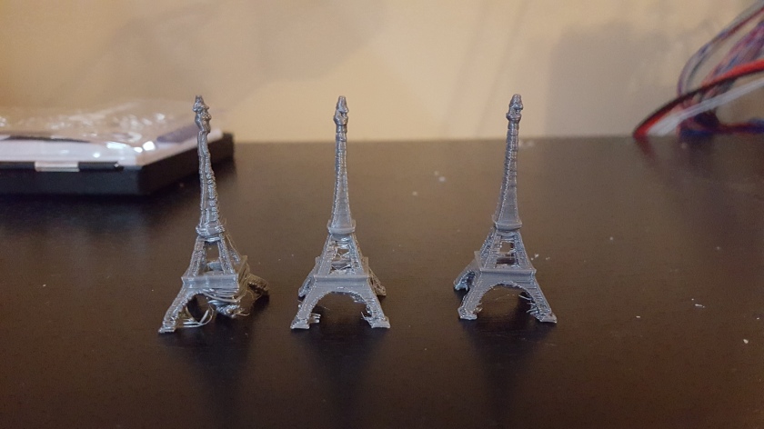
Since I’ve had my printer for a couple of months I’ve already made a bunch of different random objects, and at first my test of quality was a miniature Eiffel Tower model. In fact that was the first thing I printed.
As you can see it didn’t go too well. However thats no reason to give up, and I quickly improved after just 3 more prints.
And finally after a couple more weeks of fine tuning I returned to the Eiffel Tower and the result was pretty good for such a small object.
It was after that print that I started moving onto to other objects. The link to that Eiffel Tower model is here.
What about right now?
Currently I’m doing one final test I had for my printer, then I’ll be jumping right in to making 3D Printed instruments. That last test is creating a fully functional and completely 3D Printed Rubik’s Cube, using this model. I’m nearly done with it and I’ve learned a lot about functional printing through making it. It has also given me a priorities of modifications I want to make to my 3D printer before I offer services on 3D hubs to increase the print quality. Right now I’m experimenting with different cooling fan setups, and I plan on writing more updates about each modification as I do them. For now, here’s a rough list of everything I will want to do before using 3D Hubs:
Design and print a spool holder
Add more active cooling
Use a Raspberry Pi to control printer via octoprint
Install a z-probe to enable automatic heated bed leveling
Once all those modifications are done I will hopefully be able to open up my own hub, and by then hopefully be well underway into creating 3d printable instruments.
I hope you enjoyed the post, see you in the next update.